|
|
|
Traffic Light Control Using AT89C51
By: Arif Johar Taufiq

Project
Here are presented a small example of a simple
traffic light control projects with microcontroler AT89C51 to four conditions.
This example project can you develop itself into three traffic
lights and two state (phase).
Traffic lights 4
states or four poles means that one cycle consists of four state lights. The
situation is more clear lights can be seen in Table 4.1 for the output lights
used at UC AT89C51 port
East
Port 1.0 = Red lamp
Port 1.1 = Yellow lamp
Port 1.2 = Green lamp
|
South
Port 1.3 = Red lamp
Port 1.4 = Yellow lamp
Port 1.5 = Green lamp
|
West::
Port 3.0 = Red lamp
Port 3.1 = Yellow lamp
Port 3.2 = Green lamp
|
North:
Port 3.3 = Red lamp
Port 3.4 = Yellow lamp
Port 3.5 = Green lamp
|
Example easily turn on the lights Red, Yellow and
Green on the eastern side of the road looking at the pictures .1 for the other
side of the road is the same idea.
NOTE:
If the lamp driver
circuit is too sensitive, the input base resitor tip of 4.7 K ohm pull down
resistor can be plugged into groundi
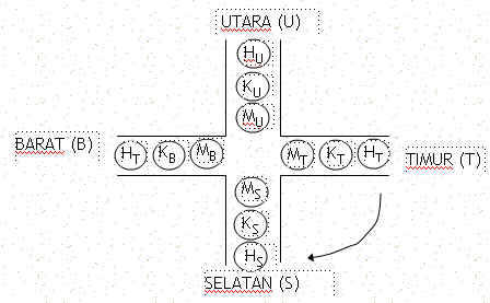
Gambar 1. Driver ke lampu LED
Traffic lights working chart
four light poles are designed as follows:

Gambar 2. Arah perubahan nyala lampu

To turn on the lights, microcontroller sends a signal
to the port-related high.
Here flame lamp
requires a high input for the lamp drivers, because the design of such drivers
in the figure 4.1, the first transistor in the off state. So if you get a high
input from the port teraliri base current registration:
Ib= (Vport-Vbe)/4,7k ohm Ampere
This current
is enough to make working transistors will be saturated so that the LED current
from the VCC :
Iic= (Vcc-VLED)/560ohm Ampere
Suppose we want a green light east (HT) and all the
other red, send data to port 1 = 0CH (00001100b) and port3 = 09H (00001001b)
So that the program is written as follows, for the sake of
convenience delay is not counted in minutes that precision.
If you want more detailed reference clock can be used by
programmers at uC timer.
;-----------------------------------
; PROGRAM TRAFFIC LIGHT
; By : Arif Johar Taufiq
; http://guru.technosains.com
;-----------------------------------
ORG 00H
LJMP K1
ORG 100H
K1: MOV P1,#09H ; MERAH SEMUA
MOV P3,#09H
ACALL TUNDA
K2: MOV P1,#0CH
MOV P3,#09H
ACALL TUNDA
K3: MOV P1,#0EH
MOV P3,#09H
ACALL TUNDA
K4: MOV P1,#09H
MOV P3,#09H
ACALL TUNDA
K5: MOV P1,#21H
MOV P3,#09H
ACALL TUNDA
K6: MOV P1,#31H
MOV P3,#09H
ACALL TUNDA
K7: MOV P1,#09H
MOV P3,#09H
ACALL TUNDA
K8: MOV P1,#09H
MOV P3,#0CH
ACALL TUNDA
K9: MOV P1,#09H
MOV P3,#0EH
ACALL TUNDA
K10: MOV P1,#09H
MOV P3,#09H
ACALL TUNDA
K11: MOV P1,#09H
MOV P3,#21H
ACALL TUNDA
K12: MOV P1,#09H
MOV P3,#31H
ACALL TUNDA
LJMP K1
TUNDA: MOV R7,#00H
ULANG2: MOV R6,#00H
ULANG1: MOV R5,#00H
ULANG: INC R5
CJNE R5,#02H,ULANG
INC R6
CJNE R6,#02H,ULANG1
INC R7
CJNE R7,#02H,ULANG2
RET
END
Download
Program-1
To be more flexible in its
setup delay of the light, then the program can be made like the example below,
variable delay can easily be changed
;==============================================================;
; PROGRAM SIMULASI LAMPU LALULINTAS ;
; by: ARIF JOHAR TAUFIQ ;
; http://guru.technosains.com
;==============================================================;
; POSOSI LAMPU: ;
; ;
;
BARAT ;
;
H (P1.2) ;
;
K (P1.1) ;
;
M (P1.0) ;
; ;
; SEL H K M
M K H UTARA ;
; (P3.6) (P3.5) (P3.4) (P3.0) (P3.1) (P3.2) ;
; ;
;
M (P1.4) ;
;
K (P1.5) ;
;
H (P1.6) ;
;
TIMUR ;
;==============================================================;
TD_RED EQU 03H ;waktu tunda merah 3 dtk //dapat diubah
TD_GREEN EQU 05H ;waktu tunda hijau 5 dtk //dapat diubah
TD_YELLOW EQU 02H ;waktu tunda kuning 2 dtk //dapat diubah
ORG 00H
LJMP AWAL
;==================
;LAMPU BARAT
;==================
ORG 100H
AWAL: MOV R2,#00H
BARAT_1: ACALL ALL_RED ; semua MERAH
MOV A,#00H
AA: ACALL TUNDA
INC A
CJNE A,#TD_RED,AA
BARAT_2: MOV P1,#14H ; hijau barat
MOV P3,#11H
MOV A,#00H
BB: ACALL TUNDA
INC A
CJNE A,#TD_GREEN,BB
BARAT_3: MOV P1,#12H ; kuning barat
MOV P3,#11H
MOV A,#00H
CC: ACALL TUNDA
INC A
CJNE A,#TD_YELLOW,CC
;==================
; LAMPU UTARA
;==================
UTARA_1: ACALL ALL_RED ;semua merah
MOV A,#00H
DD: ACALL TUNDA
INC A
CJNE A,#TD_RED,DD
UTARA_2: MOV P1,#11H ;hijau utara
MOV P3,#14H
MOV A,#00H
EE: ACALL TUNDA
INC A
CJNE A,#TD_GREEN,EE
UTATA_3: MOV P1,#11H ;kuning utara
MOV P3,#12H
MOV A,#00H
FF: ACALL TUNDA
INC A
CJNE A,#TD_YELLOW,FF
;=================
; LAMPU TIMUR
;=================
TIMUR_1: ACALL ALL_RED ;semua merah
MOV A,#00H
GG: ACALL TUNDA
INC A
CJNE A,#TD_RED,GG
TIMUR_2: MOV P1,#41H ;hijau timur
MOV P3,#11H
MOV A,#00H
HH: ACALL TUNDA
INC A
CJNE A,#TD_GREEN,HH
TIMUR_3: MOV P1,#21H ;kuning timur
MOV P3,#11H
MOV A,#00H
II: ACALL TUNDA
INC A
CJNE A,#TD_YELLOW,II
;==================
; LAMPU SELATAN
;==================
SELATAN_1: ACALL ALL_RED ;semua merah
MOV A,#00H
JJ: ACALL TUNDA
INC A
CJNE A,#TD_RED,JJ
SELATAN_2: MOV P1,#11H ;hijau selatan
MOV P3,#41H
MOV A,#00H
KK: ACALL TUNDA
INC A
CJNE A,#TD_GREEN,KK
SELATAN_3: MOV P1,#11H ;kuning selatan
MOV P3,#21H
MOV A,#00
LL: ACALL TUNDA
INC A
CJNE A,#TD_YELLOW,LL
INC R2
CJNE R2,#03H,MAJU
SJMP SUS
MAJU: LJMP BARAT_1
SUS: MOV A,#00H
RENE: ACALL ALL_OFF
ACALL TUNDA
ACALL ALL_YL
ACALL TUNDA
INC A
CJNE A,#05,RENE
LJMP AWAL
;======================
; PROSEDUR SEMUA MERAH
;======================
ALL_RED: MOV P1,#11H
MOV P3,#11H
RET
;=======================
; PROSEDUR SEMUA KUNING
;=======================
ALL_YL: MOV P1,#22H
MOV P3,#22H
RET
;=======================
; PROSEDUR SEMUA MATI
;=======================
ALL_OFF: MOV P1,#00H
MOV P3,#00H
RET
;======================
; PROSEDUR TUNDA ; 1 detik xtal 12mhz
;======================
TUNDA: MOV R1,#00H
WIH: MOV R0,#0h
LAGI: MOV TMOD,#01h
MOV TH0,#0D8h
MOV TL0,#0EFh
SETB TR0
ULANG: JBC TF0,HITUNG
SJMP ULANG
HITUNG: INC R0
CJNE R0,#050h,LAGI
INC R1
CJNE R1,#02H,WIH
RET
Download
Program-2
|
|